


Special offers from our partners!

Find Replacement BBQ Parts for 20,308 Models. Repair your BBQ today.
SBB00104-3-0309Page 18
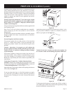
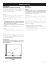
GAS CONVERSION TO LIQUID PROPANE GAS
A conversion kit to liquid propane (LP) gas is included with your
grill.
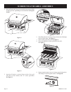
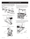
1. Remove cooking grids and ame tamer from grill.
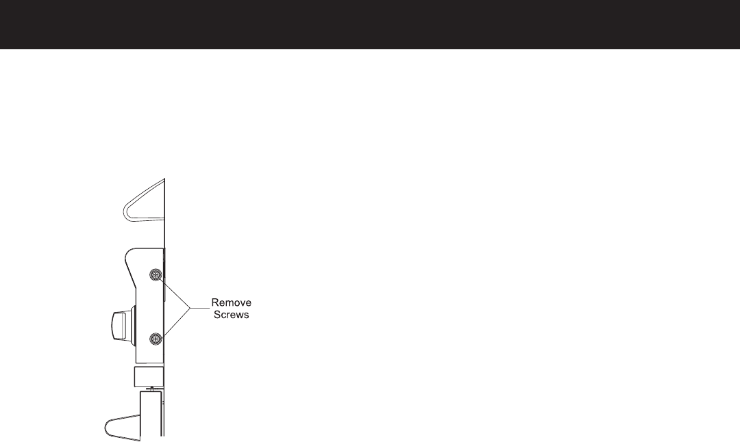
2. Use allen wrench supplied in conversion kit to remove control
knobs.
3. Remove control panel (4 Phillips screws).
Figure 19
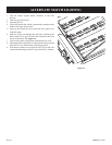
4. Use a 7mm socket or wrench to remove all natural gas orices
marked 53 from gas valves.
5. Install LP gas orices marked 1.02 into gas valves. Apply pipe
compound to threads on orices prior to installation.
6. Attach left side of control panel to grill with two (2) Phillips
screws from Step 3. Carefully insert left burner orice into left
burner. Continue to carefully insert the remaining orices into
the burners. Attach right side of control panel to grill with two
(2) Phillips screws from Step 3.
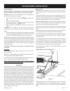
7. The low input adjustment screws are located inside the main
burner valve stems. Use small screwdriver supplied in conver-
sion kit to turn each adjustment screw clockwise 1/4 turn (90
degrees).
The valve stem that is second from the left side of the grill is
the rotisserie valve stem and it will not be adjusted.
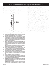
8. Remove rotisserie burner back cover (5 Phillips screws - four
on the back and one on inside top of the back of the grill).
9. Use a 14mm wrench or adjustable wrench to remove natural
gas rotisserie orice marked 1.51 from orice tting.
10. Install LP gas rotisserie orice marked 1.02 into orice tting.
Apply pipe compound to threads on orice prior to installa-
tion.
11. Remove the exible gas line from manifold.
12. Connect the hose and regulator (no included) to manifold with
an adjustable wrench. Please contact your dealer to order the
necessary parts for your Broilmaster grill.
13. Attention: Before lighting your grill check all gas connections
including the adjustment screws in valve stems for gas leaks
with a soapy water mixture.
Caution: Do not use the grill if a gas leak is detected until gas
leak is corrected. If a gas leak can not be stopped, do not use
grill. You must contact a qualied repair person.
14. Replace back panel (5 Phillips screws from step 8).
15. Replace all control knobs with allen wrench.
16. Apply the completed conversion label adjacent to the rating
plate label on the rear panel of the grill.
17. Ignite burners on grill and observe ame pattern. If ame is
yellow in color or ame is lifting off burner, the air shutter on
burners will require adjustment.
18. Turn OFF (but do NOT remove) LP gas supply to grill.
19. Loosen (but do NOT remove) two (2) Phillips screws at end
of each burner. Lift upward and pivot burner out of grill.
20. Loosen Phillips screw at air shutter. Air shutter for LP gas
should have about 1/8” opening. Open air shutter for a yellow
ame or close air shutter for a lifting ame. Tighten Phillips
screw at air shutter.
21. Replace burners into grill. Tighten two (2) Phillips screws at
end of each burner.
22. Ignite burners on grill to verify burner ame characteristics.
Installation must conform to local codes or, in the absence of local
codes, with the National Fuel Gas Code, ANSI Z223.1. In Canada,
installation shall be in accordance with CAN/CGA-B149.1 Natural
Gas Installation Code, and local codes where applicable. Contact
your local gas company for code regulations, recommended pro-
cedures, and the installation of your grill’s gas supply line.