


Special offers from our partners!

Find Replacement BBQ Parts for 20,308 Models. Repair your BBQ today.

Page 8 B100999-1-0906
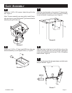
Install one 1/4-20 x 3/4 phillips head screw into the factory
installed nut on the Left Side of cart. Figure 3.
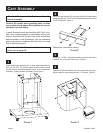
Attach base body assembly (6) to base shelf assembly (8)
with six 1/4-20 x 3/4" phillips head screws. Insert screws
into the factory installed threaded inserts on the base shelf
assembly. Tighten screws completely. See Figure 1.
Attach drip pan bracket (5) to the rear brace of the base body
assembly with two 1/4-20 x 3/4 phillips head screws and two
1/4-20 Wing Nuts. Figure 2.
FIGURE 2
FIGURE 1
FIGURE 2
Fasten the Cylinder Retainer (3) to the screw with a wing nut.
Adjust height to accommodate your LP cylinder. Figure 3.
CART ASSEMBLY
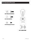
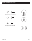
Attention: Peel protective film from all parts
before assembly.
Caution: Be careful when handling parts, as they
may contain sharp edges. Work gloves are recom
-
mended to prevent injury.
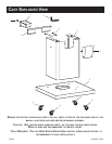
In each illustration parts are identified with "Key" num
-
bers. Key numbers appear in parenthesis after a part
name is mentioned for the first time in the instructions
and are labeled on the illustrations. You can reference
each part by its key number on the Parts List if you need
help in identifying a part.
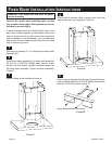
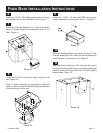
Attention: For fixed base installation instruc
-
tions, turn to page 10.
1
2
3
4
FIGURE 3
(Base body removed for clarity)