


Special offers from our partners!

Find Replacement BBQ Parts for 20,308 Models. Repair your BBQ today.

9
7
10
8
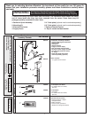
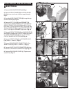
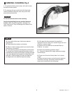
TOOLS REQUIRED
1 Channel Locks
2 Adjustable Wrench
3 Plumbers' Putty or
Caulking
4 Phillips Screwdriver
12 3
456 7
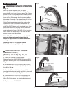
INSTALL SPOUT ASSEMBLY;
Fig. 1
INSTALLATION
CAUTION
Turn off hot and cold water
supplies before beginning
2
10'
1
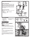
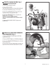
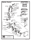
Roughing-in Dimensions
1. (Optional) Assemble DECK PLATE (1) and PUTTY
PLATE (2) to FAUCET BODY (3) with SCREW (4). Fig.
1.
2. Insert WIRES (5), FLEX HOSE (6) and SPOUT
SHANK (7) through center hole of mounting surface.
Fig. 1a.
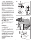
3. Assemble "C" WASHER (8) and LOCKNUT (9)
onto threads of SPOUT SHANK (7) from underside of
mounting surface. Fig. 1b.
4. Align FAUCET (3) and tighten LOCKNUT (9). If using
DECK PLATE (1) hand tighten DECK PLATE SPIN
NUTS (10) to secure FAUCET (3) to mounting surface.
Fig. 1b.
Fig. 1a
Fig. 1b
5
7
6
Fig. 1
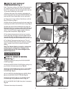
GENERAL DESCRIPTION:
Electronic faucet with proximity operation. Colored
LED's signal temperature change mode. Vandal
resistant solid brass construction single post mounting.
Operates on AC permanent power. Water pressure
range from 20 to 80 psi. In-line strainer for solenoid is
integral. Single inlet 3/8 compression, built-in checks,
and flexible stainless steel 15" reach inlet hose for
spout connection.
114mm
(4-1/2)
270mm MAX.
(10-5/8)
175mm MAX.
(6-7/8)
1524mm
(60)
125mm
(4-7/8)
3/8" COMP.
81mm
(3-3/16)
508mm
(20)
132mm
(5-3/16)
55mm D.
(2-3/16)
143mm
(5-5/8)
183mm
(7-3/16)
381mm
(15)
3/8"
COMP.
3/8"
COMP.
25mm MAX.
(1)
190mm
(7-7/16)
CODES AND STANDARDS:
These products meet or exceed the following coded
standards:
ANSI A117.1
ASME A112.18.1
CSA B 125
NSF 61/Section 9
ADA Compliant
5 Flat Blade Screwdriver
6 Electric Drill & 1/4" Drill Bit
7 Tape Measure
4
1
2
3
M968857 REV.1.2