


Special offers from our partners!

Find Replacement BBQ Parts for 20,308 Models. Repair your BBQ today.

7
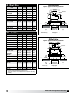
Model G/GB Centrifugal Roof Exhaust Fans
®
IMPORTANT
Adjust (tighten) belt tension after the first 24-48 hours
of operation.
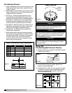
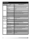
Inspection
Inspection of the fan should be conducted at the first
30 minute and 24 hour intervals of satisfactory operation.
30 Minute Interval
Inspect bolts, setscrews and motor mounting bolts.
Adjust and tighten as necessary.
24 Hour Interval
Check all internal components. On GB unit only, inspect
belt alignment and tension. Adjust and tighten as
necessary.
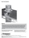
Maintenance: G / GB
Installation and maintenance are to be performed only
by qualified personnel who are familiar with local codes
and regulations and who are experienced with this type
of equipment.
Motor maintenance is generally limited to cleaning and
lubrication (where applicable). Cleaning should be limited
to exterior surfaces only. Removing dust buildup on
motor housing ensures proper motor cooling.
WARNING
Always disconnect, lock and tag power source before
servicing. Failure to disconnect power source can
result in fire, shock or serious injury.
Greasing of motors is only intended when fittings are
provided. Many fractional horsepower motors are
permanently lubricated and should not be lubricated
after installation. Motors supplied with grease fittings
should be greased in accordance with manufacturers’
recommendations. Where motor temperatures do not
exceed 104ºF (40ºC), the grease should be replaced after
2,000 hours of running time as a general rule.
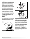
Wheels require very little attention when moving clean
air. Occasionally, oil and dust may accumulate causing
imbalance. When this occurs, the wheel and housing
should be cleaned to ensure smooth and safe operation.
All fasteners should be checked for tightness each
time maintenance checks are performed prior to
restarting unit.
A proper maintenance program will help these units
deliver years of dependable service.
CAUTION
Uneven cleaning of the wheel will produce an out of
balance condition that will cause vibration in the fan.
WARNING
This unit should be made non-functional when cleaning
the wheel or housing (fuses removed, disconnect
locked off).
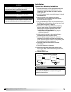
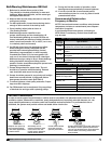
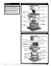
11. Belt tension can be adjusted by loosening four
fasteners on the drive frame, see Figure 11. The
motor plate slides on the slotted adjusting arms
and drive frame angles in the same manner.
12a. Sizes 071-161: Belts should be tensioned just
enough to prevent slippage at full load.
Note: Belts should have a slight bow on the slack
side while running at full load (see Figure 12a).
12b. Sizes 180-540: Belt tension should be adjusted to
allow
1
⁄64 in. (0.397 mm) of deflection per inch of belt
span. For example, a 15 in. (381 mm) belt span should
have
15
⁄64 in. (0.234 mm) (or about
1
⁄4 in. (6 mm)) of
deflection with moderate thumb pressure at mid-point
between pulleys (see Figure 12b).
13. The adjustable motor pulley is factory set for the
RPM specified. Speed can be increased by closing
or decreased by opening the adjustable motor pulley.
14. Any increase in speed represents a substantial
increase in the horsepower required by the unit.
15. Motor amperage should always be checked to avoid
serious damage to the motor when speed is varied.
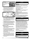
Operation: G / GB
1. Before starting up or operating fan, check all
fasteners for tightness. In particular, check the
setscrews in wheel hub.
2. While in the OFF position or before connecting the
fan to power, turn the fan wheel by hand to be sure it
is not striking the venturi or any obstacle.
3. Start the fan and shut it off immediately to check
rotation of the wheel with directional arrow in the
motor compartment.
4. When the fan is started, observe the operation and
check for any unusual noises.
5. With the system in full operation and all ductwork
attached, measure current input to the motor and
compare with the nameplate rating to determine if
the motor is operating under safe load conditions.
6. Keep inlets and approaches to fan clean and free
from obstruction.
Slack
Side
Deflection
Figure 12a Figure 12b
Fasteners
(4) *Fasteners
*Identical fasteners on
opposing side must also
be loosened.
Figure 11