


Special offers from our partners!

Find Replacement BBQ Parts for 20,308 Models. Repair your BBQ today.

6
Adding extended features to a Phaser® 340 — Upgrade Kit Z340FX
Replacing the print engine ROM
9.
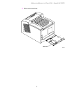
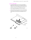
Locate the print engine ROM.
Note
Some products may use a standard ROM IC chip while others may
use an adaptor circuit board. Either part type can be substituted for
the other on this main board.
10.
Insert the IC removal tool between the ROM (or adaptor board ROM)
and the socket.
GENTLY
remove the old part by prying upward,
being careful to not damage the main board. When the near end of the
part begins to lift from the socket, gently lift the other end of the part
with your fingers to prevent damage to the ROM’s pins.
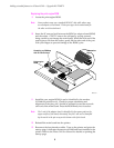
11.
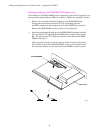
Install the new engine ROM (it can be identified by the number
163-0646-00 printed on it). Check for proper orientation and
alignment of the pins; pin 1 should be oriented toward the network
card end of the main board. Press the ROM firmly into its socket.
Note
Pin 1 end of the adaptor board is identified by the square pads on the
upper surface of the board; alternately, the pin 1 end can be identified
by the notch in the pin array on the bottom-side of the board.
12.
Reinstall the main board into the printer.
13.
Reconnect the host interface cables. Turn on the printer and print the
startup page; it indicates the amount of RAM and fonts installed in the
printer. Refer to the
Phaser 340 User Manual
for details on printing the
startup page.
Z340-1-01
Print engine
ROM
Carefully pry ROM up
with IC removal tool
Orientation
Notch