


Special offers from our partners!

Find Replacement BBQ Parts for 20,308 Models. Repair your BBQ today.
9
107034
OWNER’S MANUAL
For more information, visit www.desatech.com
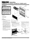
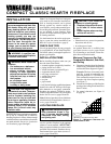
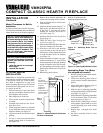
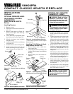
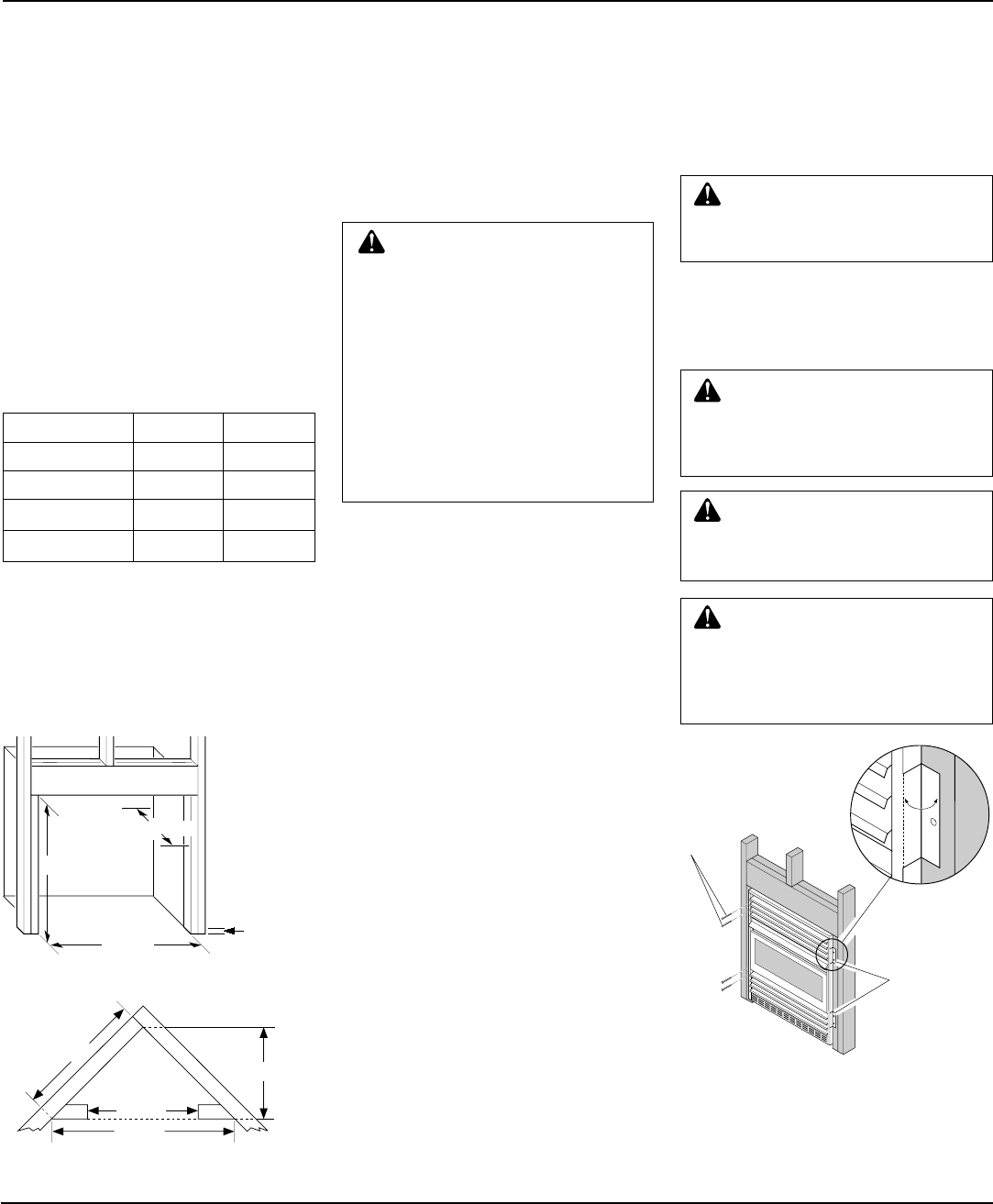
Figure 10 - Attaching Fireplace to Wall
Studs
Nailing
Flanges
Nails or
Wood
Screws
INSTALLATION
Continued
2. If installing GA3400T blower acces-
sory, do so at this time. Follow instruc-
tions included with blower accessory.
Note:
If not installing blower acces-
sory, you may wish to run electrical
wiring to your fireplace for future
blower installation (see Accessories,
page 28 and 29). Use only approved
three-wire electrical wiring.
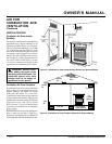
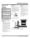
36 5/8"
25 7/8"
51 3/4"
26 7/8"
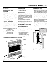
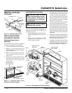
Figure 9 - Rough Opening for Installing in
Corner
BUILT-IN FIREPLACE
INSTALLATION
Built-in installation of this fireplace involves
installing fireplace into a framed-in enclo-
sure. This makes the front of fireplace flush
with wall. An optional brass trim kit acces-
sory is available (see Accessories, pages 28
and 29). Brass trim will extend past sides of
fireplace approximately 1/2 inch. This will
cover the rough edges of the wall opening.
If installing a built-in mantel above the
fireplace, but you must follow the clear-
ances shown in Figure 11, page 10. Follow
the instructions below to install the fireplace
in this manner.
Actual Framing
Height 26" 26
7
/8"
Front Width 26
3
/4" 26
7
/8"
Depth 9
1
/2" 10
1
/2"
Bottom 3/4" 3/4"
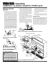
1. Frame in rough opening. Use dimen-
sions shown in Figure 8 for the rough
opening.
If installing in a corner, use dimensions
shown in Figure 9 for the rough open-
ing. The height is 26
7
/8" which is the
same as the wall opening above.
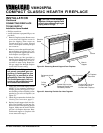
26 7/8"
26 7/8"
3/4" Off
The Floor
Minimum
10 1/2"
Figure 8 - Rough Opening for Installing in
Wall
WARNING: Do not allow any
combustible materials to overlap
the firebox front facing.
IMPORTANT:
When finishing your fire-
box, combustible materials such as wall
board, gypsum board, sheet rock, drywall,
plywood, etc. may be butted up next to the
sides and top edge of the firebox. Combus-
tible materials should never overlap the
firebox front facing.
IMPORTANT:
Noncombustible materials
such as brick, tile, etc. may overlap the front
facing, but should never cover any neces-
sary openings like louvered slots.
WARNING: Do not allow non-
combustible materials to cover
any necessary openings like lou-
vered slots.
WARNING: Use only noncom-
bustible mortar or adhesives
when overlapping the front fac-
ing with noncombustible facing
material.
WARNING: Never modify or
cover the louvered slots on the
front of the firebox.
Continued
WARNING: If pre-wiring, do
not connect wiring to any electri-
cal source at this time.
Install fireplace electrical outlet
and connect wiring to outlet be-
fore connecting to electrical
source. The fireplace electrical
outlet is included with the
GA3400T blower accessory.
Only use the fireplace electrical
outlet supplied with the GA3400T
blower accessory.
Note:
A qualified installer should make
all electrical connections.
3. Install gas piping to fireplace location.
This installation includes an approved
flexible gas line (if allowed by local
codes) after the equipment shutoff
valve. The flexible gas line must be the
last item installed on the gas piping.
4. If you have not assembled firebox, fol-
low instructions on page 4.
5. Carefully set fireplace in front of rough
opening with back of fireplace inside
wall opening.
6. Attach flexible gas line to fireplace gas
regulator. See Connecting Fireplace to
Gas Supply, page 14.
7. Bend four nailing flanges on outer cas-
ing with pliers (see Figure 10).
8. Attach fireplace to wall studs using
nails or wood screws through holes in
nailing flange.
9. Check all gas connections for leaks. See
Checking Gas Connections, page 15.
10. If using optional brass trim kit, install
the trim after final finishing and/or
painting of wall. See instructions in-
cluded with brass trim accessory for at-
taching brass trim.