


Special offers from our partners!

Find Replacement BBQ Parts for 20,308 Models. Repair your BBQ today.
17
107034
OWNER’S MANUAL
For more information, visit www.desatech.com
INSTALLATION
Continued
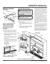
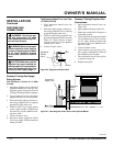
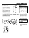
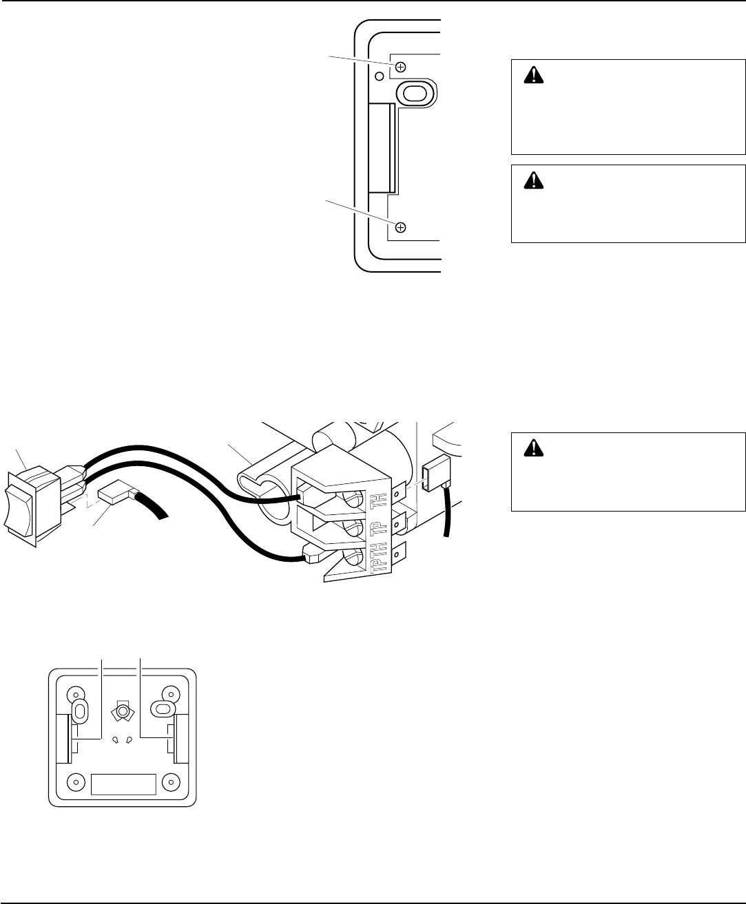
Figure 33 - Connecting Wire Terminals
OPTIONAL WALL SWITCH -
GWMS2
WARNING: Do not connect
this switch to any electrical
source! Electrical shock and/or
fire hazard will occur.
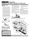
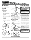
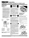
6. Connect one bare wire end to each ter-
minal (“W” and “R”) of the thermostat
base (see Figure 35).
7. Install the base onto the wall with the
provided screws.
8. Move the temperature adjustment back
and forth to insure the bimetal is free
from restrictions.
9. Replace the cover onto the base. (Upon
installation, the thermostat must be al-
lowed to stabilize at room temperature
for a minimum of 30 minutes for
proper operation).
10. Set switch on heater to Auto position.
11. Set the temperature adjustment to the
desired setting. This thermostat has been
electronically calibrated at the factory.
No adjustment or leveling is necessary.
1.
Connect one terminal of 25 ft. wire to
bottom contact of switch (see Figure 33)
.
2. Connect remaining wire terminal to the
“TH” terminal on the control valve.
Make sure that wire terminals are in
the positions on your unit as pictured
in Figure 33. If wires are not “crossed”
the thermostat will not work.
3.
Route the 25 ft. wire to a convenient
location to mount your wall switch (no
outside walls).
WARNING: Do not connect
the switch to a power source.
Electrical shock and/or fire haz-
ard will occur.
WARNING: Read and follow
installation instructions. Instal-
lation should be done by a quali-
fied installer familiar with low-
voltage wiring procedures.
AUTO
OFF
ON
One
terminal of
25 ft. wire
Switch on Gas
Heater
To Wall
Thermostat
or Switch
To Wall
Thermostat or
Switch
Control
Valve
Figure 34 - Back View of Thermostat Base
Feed wires through
rectangular slots
W
R
Figure 35 - Thermostat Base Terminals
“W” and “R”
Terminal “W”
Terminal “R”
IMPORTANT:
The wire may be shortened
but must not be lengthened.
4. Connect one bare wire end to each of
the terminals of the provided wall switch.
5. Install the wall switch and cover in
the wall.