


Special offers from our partners!

Find Replacement BBQ Parts for 20,308 Models. Repair your BBQ today.
13
107034
OWNER’S MANUAL
For more information, visit www.desatech.com
CONNECTING TO GAS
SUPPLY
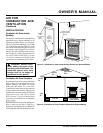
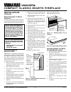
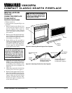
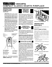
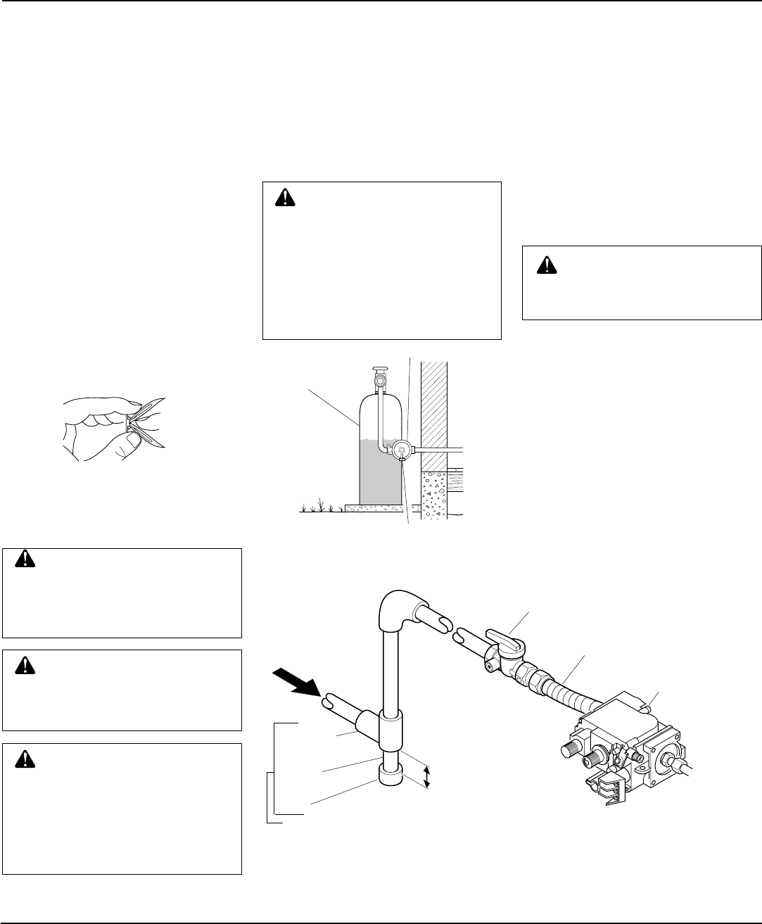
Figure 22 - External Regulator with Vent
Pointing Down
WARNING: A qualified ser-
vice person must connect fire-
place to gas supply. Follow all
local codes.
CAUTION: Never connect fire-
place directly to the propane/LP
supply. This fireplace requires
an external regulator (not sup-
plied). Install the external regula-
tor between the fireplace and pro-
pane/LP supply.
CAUTION: Use only new,
black iron or steel pipe. Inter-
nally-tinned copper tubing may
be used in certain areas. Check
your local codes. Use pipe of 1/2"
or greater diameter to allow
proper gas volume to fireplace. If
pipe is too small, undue loss of
pressure will occur.
CAUTION: Use pipe joint seal-
ant that is resistant to liquid pe-
troleum (LP) gas.
The installer must supply an external regu-
lator. The external regulator will reduce
incoming gas pressure. You must reduce
incoming gas pressure to between 11 and
14 inches of water. If you do not reduce
incoming gas pressure, fireplace regulator
damage could occur. Install external regu-
lator with the vent pointing down as shown
in Figure 22. Pointing the vent down pro-
tects it from freezing rain or sleet.
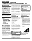
We recommend that you install a sediment
trap in supply line as shown in Figure 23.
Locate sediment trap where it is within
reach for cleaning. Install in piping system
between fuel supply and heater. Locate sedi-
ment trap where trapped matter is not likely
to freeze. A sediment trap traps moisture
and contaminants. This keeps them from
going into fireplace controls. If sediment
trap is not installed or is installed wrong,
fireplace may not run properly.
Propane/LP
Supply Tank
Vent Pointing Down
External Regulator
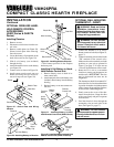
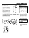
Attaching Wood Base to Solid
Floor
For attaching base to solid floors (concrete
or masonry)
Note:
Floor anchors and mounting screws
are in hardware package. The hardware pack-
age is provided with fireplace.
1. Drill holes at marked locations using
5/16" drill bit. For solid floors (concrete
or masonry), drill at least 1" deep.
2.
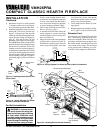
Fold floor anchor as shown in Figure 21.
3. Insert floor anchor (wings first) into
hole. Tap anchor flush to floor.
4. Insert mounting screws through base
and into floor anchors.
5. Tighten screws until base is firmly fas-
tened to floor.
Installation must include a equipment shutoff
valve, union, and plugged 1/8" NPT tap.
Locate NPT tap within reach for test gauge
hook up. NPT tap must be upstream from
fireplace (see Figure 23).
IMPORTANT:
Install equipment shutoff
valve in an accessible location. The equip-
ment shutoff valve is for turning on or
shutting off the gas to the appliance.
Apply pipe joint sealant lightly to male
threads. This will prevent excess sealant
from going into pipe. Excess sealant in pipe
could result in clogged fireplace valves.
Continued
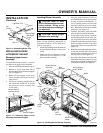
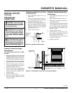
Figure 23 - Gas Connection
3" Minimum
From External
Regulator
(11" W.C.** to
14" W.C.
Pressure)
CSA/AGA Design-Certified Equipment
Shutoff Valve with 1/8" NPT Tap*
Gas Control
Approved Flexible
Gas Hose
Tee Joint
Pipe
Nipple
Cap
Sediment Trap
*Purchase the optional CSA/AGA design-certified equipment shutoff valve from your
dealer. See Accessories, pages 28 and 29.
**Minimum inlet pressure for purpose of input adjustment.
Figure 21 - Folding Anchor
INSTALLATION
Continued
WARNING: This appliance re-
quires a 45° male flare fitting 5/8"-
18 UNF (Unified National Fine
Thread) inlet connection and the
flexible gas line provided.