


Special offers from our partners!

Find Replacement BBQ Parts for 20,308 Models. Repair your BBQ today.
12
107034
COMPACT CLASSIC HEARTH FIREPLACE
VMH26PRA
®
For more information, visit www.desatech.com
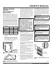
Red
Red
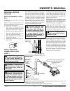
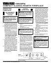
Fan Switch
(Auto/Off/On)
Blue
Blue
Thermostat
Switch
(N.O.)
Green
White
Green
White
On
110/115
V.A.C.
Blower
Motor
Black
Off
1
2
3
Auto
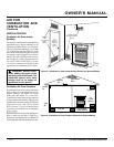
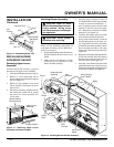
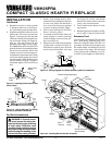
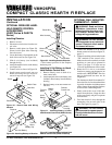
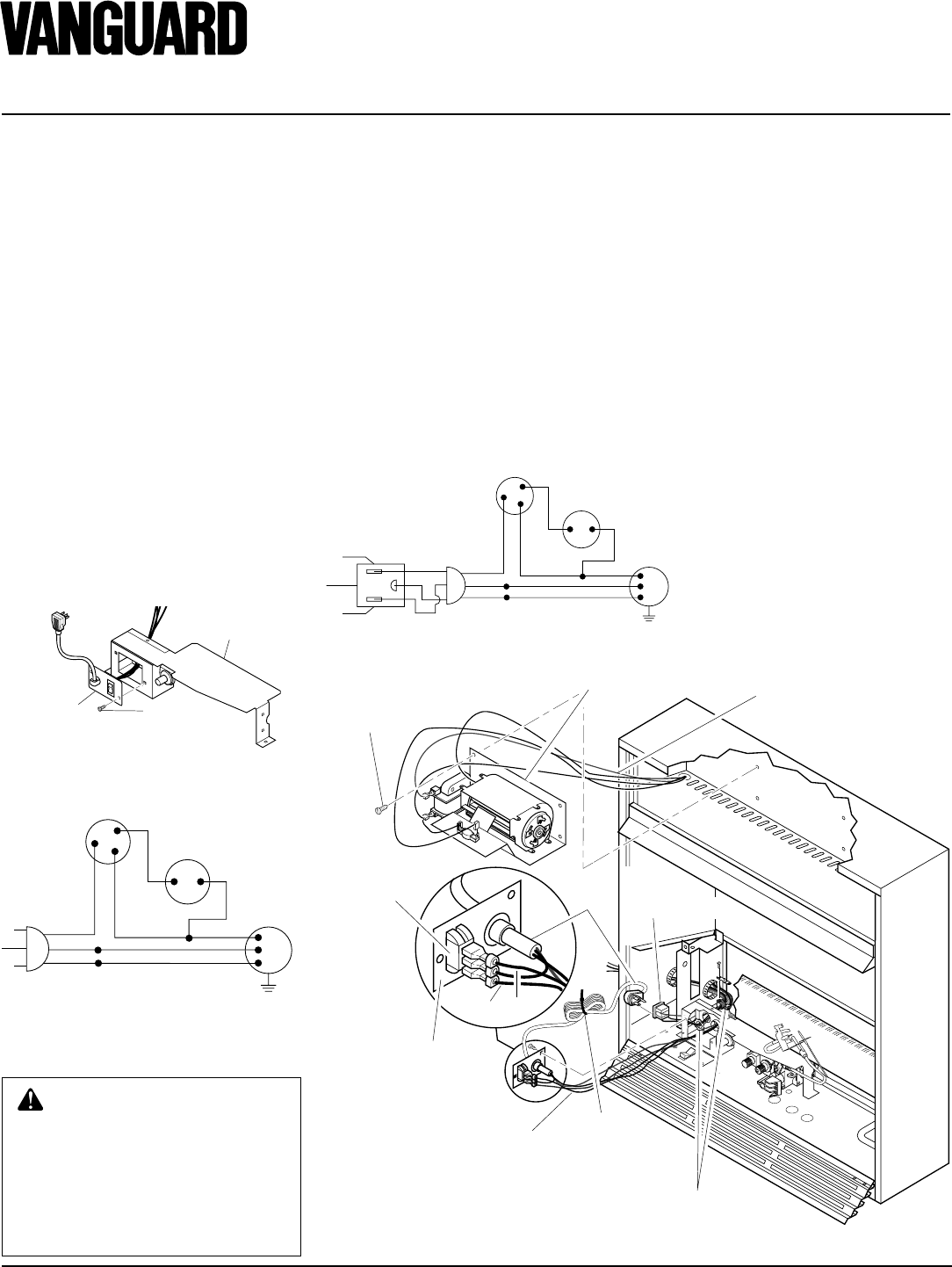
Figure 20 - Installing Blower Bracket Assembly
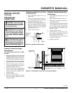
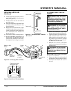
Figure 17 - Installing Switch Plate to Valve
Cover Shield
INSTALLATION
Continued
1. Install a snap bushing found in hard-
ware kit into one of the holes found rear
of valve cover shield. The other hole is
for a strain relief clamp (not supplied)
to secure incoming electrical supply.
2. Follow steps 2 through 6 in Installing
Blower Assembly, page 11.
3. A licensed electrician must follow the
wiring diagram to connect incoming
electrical supply to fan kit wiring har-
ness (see Figure 19).
4. Plug power cord to the outlet receptacle
(not provided) as shown in Figure 20.
Wind the extra cable in power cord and
and tie it up with the plastic wire strap
Figure 18 - Wiring Diagram For Blower
Accessory Standard Installation
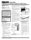
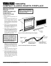
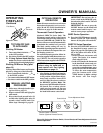
Figure 19 - Wiring Diagram For Blower Accessory Built-In Installation
Red
Red
Fan Switch
(Auto/Off/On)
Blue
Blue
Thermostat
Switch
(N.O.)
Green
White
Green
White
On
110/115
V.A.C.
Blower
Motor
Black
Off
1
2
3
Auto
For Built-In Installation
WARNING: A licensed electri-
cian must connect the wiring har-
ness to electrical supply following
all local codes. Electrician must
provide a clamp on the box cover to
secure the wiring. Wiring should be
routed through the bushing in the
hole on the outer casing of heater.
Blower Bracket Assembly
Screw
Wire
Harness
Power
Cord
Plastic
Wire
Strap
Wire
Harness
Switch
Switch
Clamp Connector
(not included)
Blue
Red
Outlet
Receptacle
(Not Supplied)
8. Reconnect red wire to switch position
3. Reconnect blue wire to switch posi-
tion 1. Reconnect green and white wires.
9. Install the switch plate on the valve cover
shield with 2 #10 screws provided (see
Figure 17). Route power cord out of the
cabinet by inserting it through the bush-
ing on the outer casing (see Figure 16,
page 11). Plug fan kit into 120-Volt
grounded power supply and test opera-
tion.
Note:
When switch is in the AUTO
position, the fan will start after the heater
has run for a few moments. The fan will
continue to run for several moments af-
ter the heater has been turned off. When
switch is in the ON position, the fan will
run until turned to OFF. Reinstall upper
louver assembly (see Figure 15, page 11)
and branch support. Close lower louver
door.
Valve Cover
Shield
Switch
Plate
Screw
(see Figure 20). Set the cable bundle
between the burner bracket and outer
casing, away from the burner.
5. Test to make sure the blower is work-
ing properly.
6. Reinstall upper louver assembly (see Fig-
ure 15, page 11) and close lower louver.
Extension Cord
Use extension cord if needed. The cord must
have a three-prong, grounding plug and a
three-hole receptacle. Make sure cord is in
good shape. It must be heavy enough to carry
the current needed. An undersized cord will
cause a drop in line voltage. This will result
in loss of power and overheating. Use a No.
16 AWG cord for lengths less than 50 feet.