


Special offers from our partners!

Find Replacement BBQ Parts for 20,308 Models. Repair your BBQ today.
11
107034
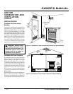
OWNER’S MANUAL
For more information, visit www.desatech.com
3
2
1
Continued
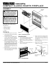
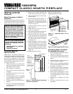
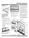
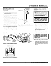
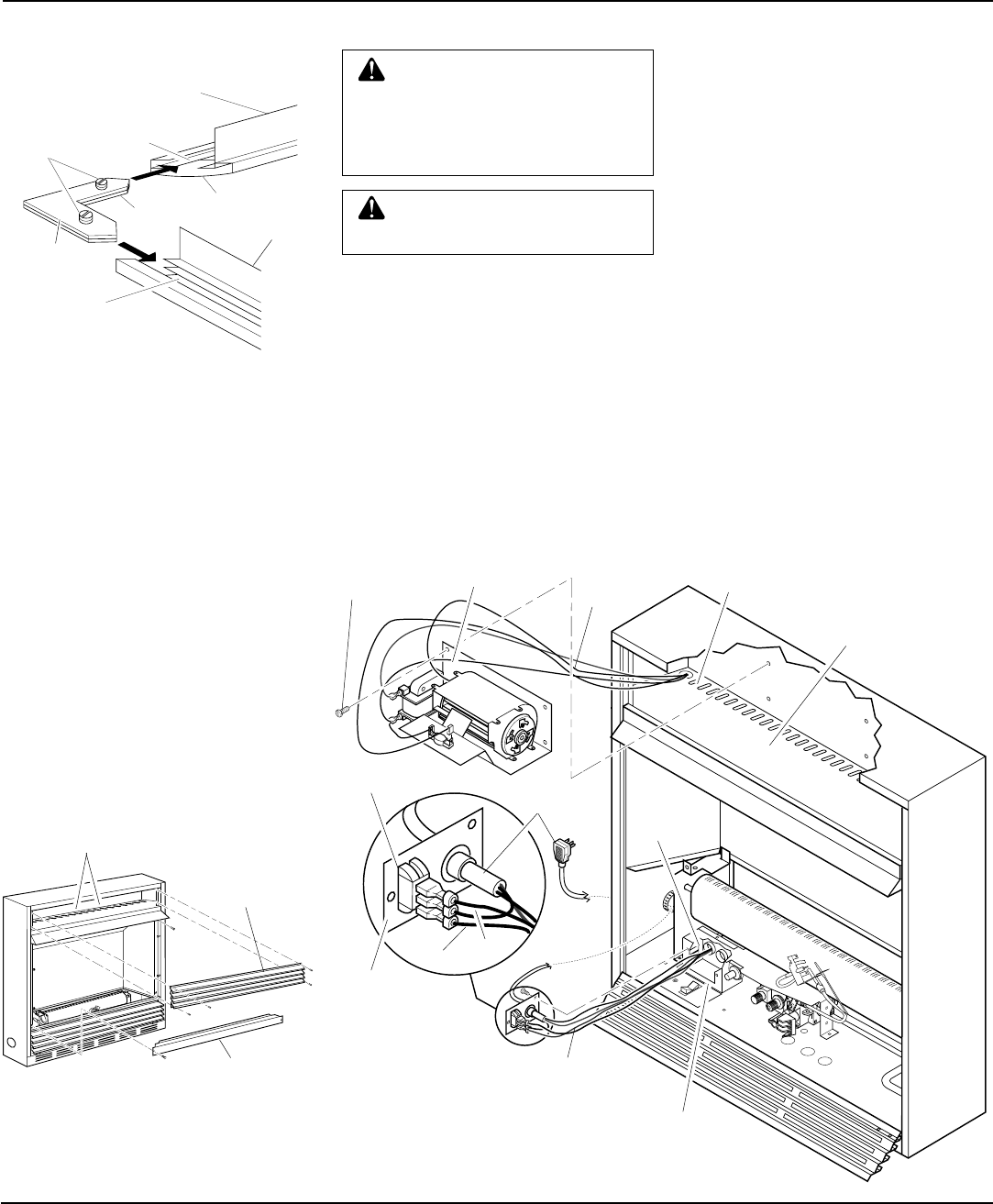
Figure 15 - Removing Upper Louver
Assembly and Branch Support
INSTALLATION
Continued
Blower Bracket
Mounting Holes
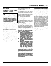
INSTALLING BLOWER
ACCESSORY GA3400T
Removing Upper Louver
Assembly
To install the blower accessory, you must
first remove the upper louver assembly.
1. Lift screen off heater and remove log set.
2. Remove 2 screws from each side of
branch support and pull branch support
out (see Figure 15).
3. Remove 4 brass-plated screws from
louver assembly (see Figure 16). Save
these screws.
4. Pull louver assembly straight out from
the cabinet. Be careful not to scratch
the paint. Set louver assembly and
screws aside.
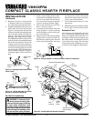
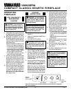
Wire
Harness
Blower Bracket
Assembly
Screw
Power
Cord
Wire
Harness
Switch
Baffle
Wiring Routing
Hole in Baffle
Switch
Plate
Blue
Red
Installing Blower Assembly
Note:
If you are using a mantel with your
heater, use the following instructions. If
your heater is built-in, see For Built-In In-
stallation on page 12.
1. Install snap bushings found in hardware
kit into both holes in rear of valve cover
shield.
2. Make sure the wire harness is firmly
connected to the terminals on the
blower bracket assembly.
Figure 16 - Installing Blower Bracket Assembly
Valve Cover
Shield
Snap
Bushing
Upper Louver
Assembly
Branch Support
CAUTION: Label all wires
prior to disconnection when ser-
vicing controls. Wiring errors
can cause improper and danger-
ous operation.
CAUTION: Verify proper
operation after servicing.
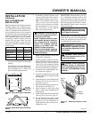
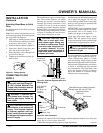
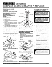
Side Brass
Trim
Top Brass Trim
Mitered Edge
Figure 14 - Assembling Brass Trim
Shim
Set
Screws
Adjusting
Plate
Slot
Slot
3. Note the wire locations on back of
AUTO/OFF/ON switch. The terminals
on back of switch are numbered 1, 2,
and 3. Carefully remove red wire from
terminal 3 and blue wire from termi-
nal 1. Black wire can remain on middle
terminal 2 (see Figure 16).
4. Carefully disconnect green and white
wires at their insulated connectors.
5. In top of the heater cabinet, locate the
four mounting holes on the outer cas-
ing. Align these four holes with those
on the blower bracket assembly. Attach
blower bracket assembly to the outer
casing with 4 #10 screws provided (see
Figure 16).
6. Route the wire harness through the hole
in left side of baffle. Pull wire harness
through lower opening on the side of
the valve shield. (see Figure 16).
7. Insert the 4 wire harness into one of the
round holes in the rear of the valve cover
shield and through the rectangular hole
in the front of shield (see Figure 16).