


Special offers from our partners!

Find Replacement BBQ Parts for 20,308 Models. Repair your BBQ today.
10
107034
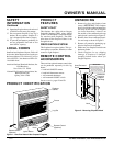
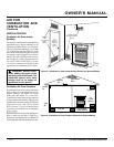
COMPACT CLASSIC HEARTH FIREPLACE
VMH26PRA
®
For more information, visit www.desatech.com
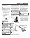
Assembling Brass Trim (Brass
trim shipped with mantel)
1. Remove packaging from three remain-
ing pieces of brass trim.
2. Locate two adjusting plates with set
screws, and two shims in the hardware
packet.
3. Align shim under adjusting plate as
shown in Figure 14, page 11.
4. Slide one end of adjusting plate/shim
in slot on mitered edge of top brass trim
(see Figure 14, page 11).
5. Slide other end of adjusting plate/shim
in slot on mitered edge of side brass
trim (see Figure 14, page 11).
6. While firmly holding edges of brass
trim together, tighten both set screws
on the adjusting plate with slotted
screwdriver.
7. Repeat steps 1 through 6 for other
corner.
8. Set brass assembly aside for later
installation.
INSTALLATION
Continued
OPTIONAL MANTEL
INSTALLATION
Note:
Refer to instructions provided with
the mantel for assembly instructions. Refer
to instructions below for system installa-
tion. Refer to instructions on page 4 for
firebox assembly. Blower accessory should
be installed if it is being used (see Accesso-
ries, pages 28 and 29).
1. Unscrew four brass screws that attach
top louver to fireplace. Remove louver
from fireplace and set aside.
2. Place fireplace on wood base.
3. Place mantel around fireplace/base
assembly.
4. Assemble brass trim kit. See Assem-
bling Brass Trim.
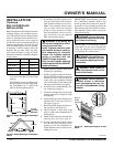
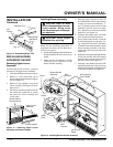
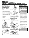
5. Firmly snap brass trim kit on shoulder
screws. Shoulder screws are located on
fireplace cabinet (see Figure 12).
6. Align brass trim kit for flush fit around
opening.
7. Use two 3" wood screws provided and
attach fireplace base to wooden base
(see Figure 12).
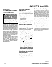
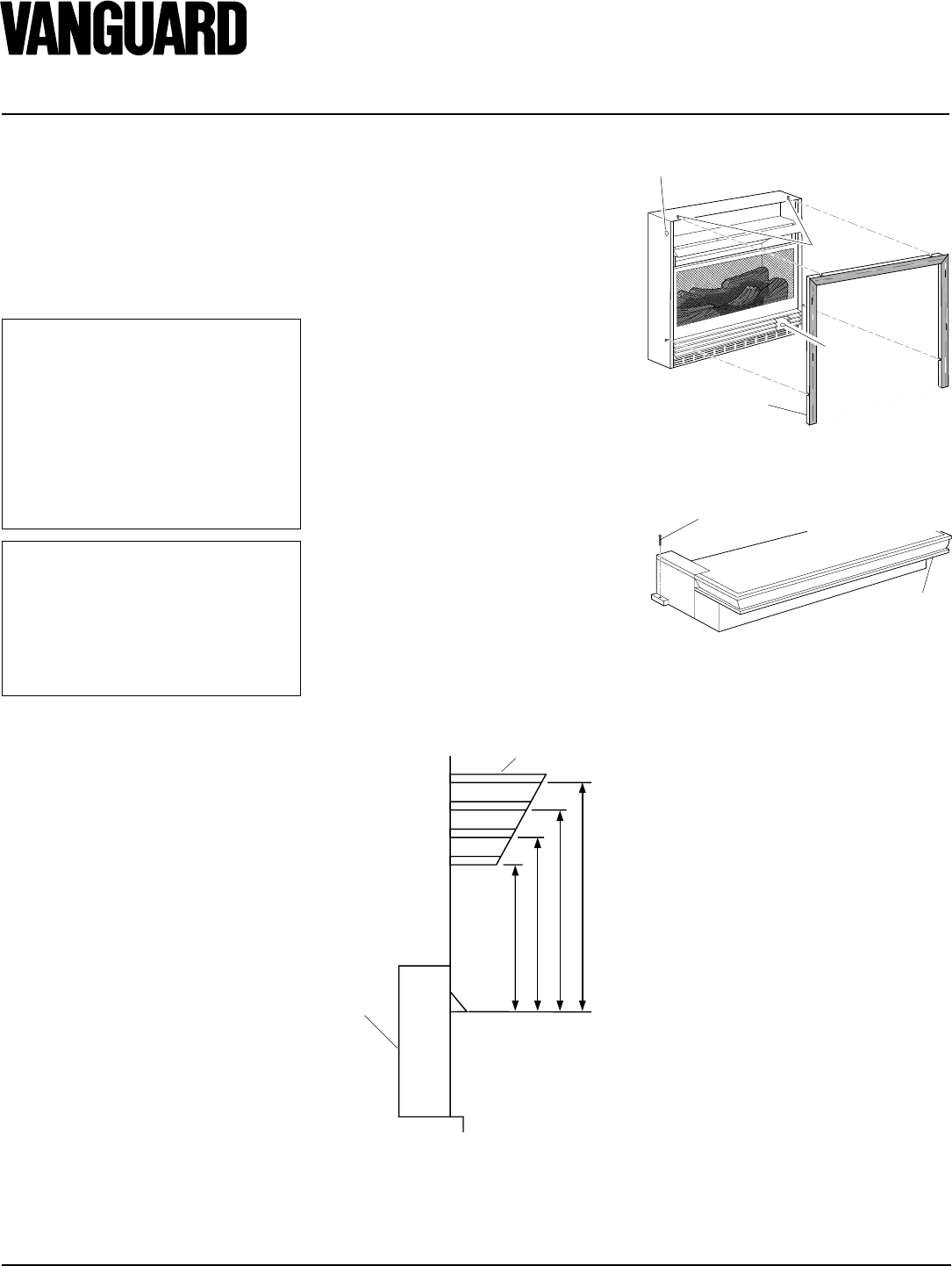
Figure 12 - Attaching Brass Trim to
Fireplace
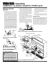
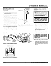
Figure 13 - Attaching Wood Base to Floor
1
3
/4" Screw
Wood
Base
8. Remove brass trim kit and mantel. Be
careful not to damage wall or mantel.
9. Place wood base next to wall at instal-
lation location.
10.
Attach wood base to floor with two 1
3
/
4
"
black screws provided (see Figure 13).
If the floor is concrete use anchor
method (see Attaching Wood Base to
Solid Floor, page 13).
11. Install gas line. See Connecting To Gas
Supply, page 13.
12. Check for leaks. See Checking Gas
Connections, page 15.
13. Place mantel around fireplace. Be care-
ful not to damage wall or mantel.
14. Place brass trim kit on the shoulder
screws located on the side and top of
the fireplace. Firmly snap the brass trim
over the shoulder screws on fireplace
(see Figure 12).
15. Adjust assembly to remove any gaps.
Attach remaining two 3" wood screws
from hardware pack through openings
inside of fireplace sides into the man-
tel. The openings are located at top be-
hind the area for the brass louvers (see
Figure 12).
16. Reinstall top brass louvers.
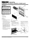
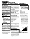
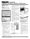
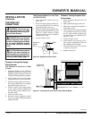
13"
16"
19"
21"
2
1
/2"
6"
8"
10"
Note:
All vertical
measurements
are from top of
fireplace
opening to
bottom of
mantel shelf. All
measurements
are in inches.
Figure 11 - Minimum Mantel Clearances
for Built-In Installation
Mantel Shelf
Side of
Firebox
Shoulder
Screws
Assembled
Brass Trim
Hole for 3"
wood screw
for attaching
fireplace to
wooden base
Hole for 3" wood screw for
attaching fireplace to mantel
Mantel Clearances for Built-In
Installation
If placing mantel above built-in fireplace,
you must meet minimum clearance between
mantel shelf and top of fireplace opening.
NOTICE: If your installation does
not meet the minimum clearances
shown, you must do one of the
following:
• raise the mantel to an accept-
able height
• remove the mantel
NOTICE: Surface temperatures of
adjacent walls and mantels be-
come hot during operation. Walls
and mantels above the firebox
may become hot to the touch. If
installed properly, these tempera-
tures meet the requirement of the
national product standard. Fol-
low all minimum clearances
shown in this manual.