


Special offers from our partners!

Find Replacement BBQ Parts for 20,308 Models. Repair your BBQ today.
7
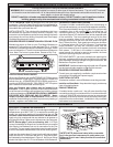
TO CONNECT TO THE GAS SUPPLY
a.
The Elite Barbecue is supplied with an approved stain-
less steel flex connector to bring the gas supply from the
gas line stub to the Valve Manifold. A 7/8”x 36” Connector
is provided with a 1/2" female pipe adapter on one end to
connect to your gas suply.
CAUTION: Use only stainless steel flex connectors that
are C.S.A. listed.
WARNING: A rubber or plastic connector will rupture or
leak, resulting in an explosion or serious injury if used
inside the Barbecue enclosure.
b. Make sure that your gas supply is turned off! Then con-
nect the 1/2" pipe adapter fitting supplied with the stainless steel
flex connector to the gas supply stub. Use pipe joint compound
that is resistant to all gasses on the male pipe fitting and tighten
securely. DO NOT use pipe joint compound to connect the
Flare Fittings.
c. Slide your Barbecue into place, making sure not to pinch or
kink the gas connector.
d. Bring the flex connector around the left-hand side of the
Barbecue. Use the Locator Angle Brackets on the left lower-
frame to position the flex connector. Continue the flex connector
along the left side to the front of the unit and the Valve Manifold
Inlet. Be careful not to block the 1" Front Vent opening as this
will obstruct Drip Tray removal.
e. Connect the flex connector to the Flare Fitting on the Mani-
fold Inlet. Support the Manifold Inlet Fitting with a wrench to
avoid applying excessive torque to the Manifold Assembly while
tightening this connection securely. DO NOT use pipe com-
pound on Flare Fittings.
IF THE OVEN IS FITTED CONTINUE WITH (f and g) BELOW.
IF IT IS SEPERATED GO TO NEXT SECTION.
f. Make sure the Barbecue Burner valves are in the "OFF"
position. Turn the gas supply on. Then carefully check all gas
connections for leaks with a brush and soapy water before
lighting. NEVER USE A MATCH OR OPEN FLAME TO TEST
FOR LEAKS.
g. Refer to the "Air Shutter Adjustment Instructions" and
"Lighting instructions" in this manual before replacing Barbecue
face and knobs.
IF THE OVEN IS SEPARATED FROM THE BARBECUE, IT
WILL REQUIRE
TWO PEOPLE TO INSTALL IT.
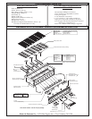
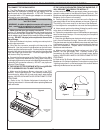
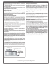
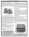
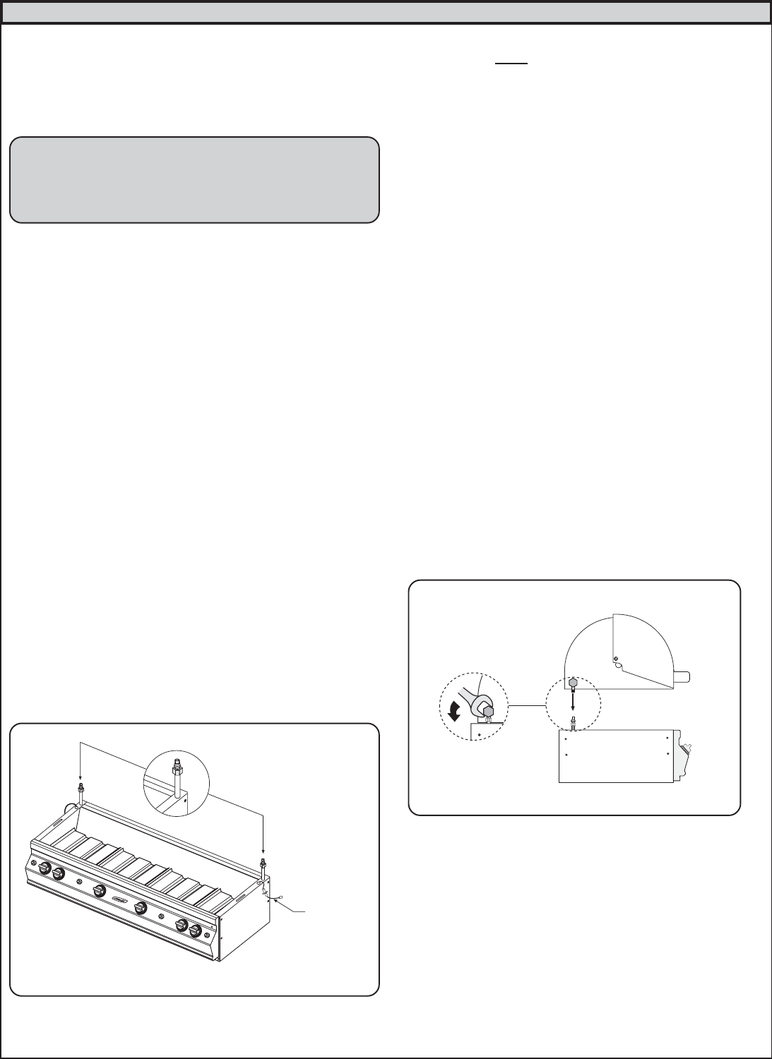
a. Make sure the Backburner gas supply tubes are protruding
above the side panels of the barbecue frame (Figure 4). The
Backburner electrode wires should be positioned outside of the
Barbecue for the Oven to sit correctly.
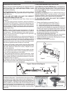
b. Carefully place the oven on the frame so the Backburner
gas supply tubes fit into lid stop elbows on the oven (Figure 6).
The front lip of the oven may sit on the face of the Barbecue.
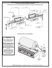
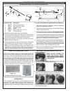
c. Hand tighten the compression nuts onto the lid stopelbows
d. Use a wrench and turn the elbow (lid stop) to push the oven
to the back of the Barbecue frame (Figure 5).
e. Tighten the compression nuts on the Backburner gas supply
tubes to the elbow lid stops. Do not use pipe joint compound
on these connections.
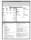
f. Place the right Backburner electrode wire through the oven
just in front of the elbow (lid stop). Secure with nut and screw.
Plug the electrode wire into the Backburner electrode (see Parts
List diagram on page 3). Make sure the electrode wire does not
touch the Backburner. Repeat above instructions for left
Backburner electrode wire.
g. Make sure the Barbecue Burner valves are in the "OFF"
position. Turn the gas supply ‘ON’. Carefully check all gas
connections for leaks with a brush and soapy water before
lighting. NEVER USE A MATCH OR OPEN FLAME TO TEST
FOR LEAKS.
h. Refer to the "Air Shutter Adjustment” instructions below, the
Backburner “Air Shutter Adjustment” instructions on page 9 and
"Lighting instructions" on the back page of this manual before
replacing the Barbecue face and knobs.
Figure 5
BACKBURNER
ELECTRODE
WIRE
Figure 4
CONNECTING YOUR ELITE 50 GOURMET BARBECUE TO THE GAS SUPPLY