


PLANNING
GUIDE
5.14
Specications subject to change without notice. Phone: (800) 793-0093www.dacor.com
Ranges equipped for installation in Canada:
■ Ranges equipped for use in Canada come pre-wired with a 4-wire,
66 inch (168 cm) long, appliance cord and NEMA 14-50P plug.
■ Do not modify the factory wiring. The plug is designed to plug directly
into a NEMA 14-50R electrical receptacle installed by a licensed
electrician.
All other models:
The conduit or appliance cord installed needs to be long enough to allow
the range to be pulled out from the wall for service, while remaining
connected. See next page for further details.
The wiring to the range must:
◊ Include a strain relief.
◊ Be terminated by tinned leads, closed loop terminals or open ended
spade lugs with upturned ends.
Where local code permits, a 3 or 4 wire appliance cord may be used. It
must:
◊ Be UL listed type SRD or SRDT.
◊ Be equipped with a NEMA 14-50P 4-wire plug
or, where local code permits, a NEMA 10-50P
3-wire plug.
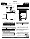
Distinctive
™
Dual Fuel Range
DR30D
Optional Backguard and Island Trim Part Numbers
Description Part Number
Island trim kit (no backguard) ADTK30
6 inch trim kit ADB3006
9 inch trim kit ADB3009
Electrical Specifications
Circuit Required Total Connected Load
240 Vac, 60 Hz., 30 Amp.* 5.7 kW (23.8 Amp.)
The ratings above are for reference only - refer to the range's product data
label for exact specifications.
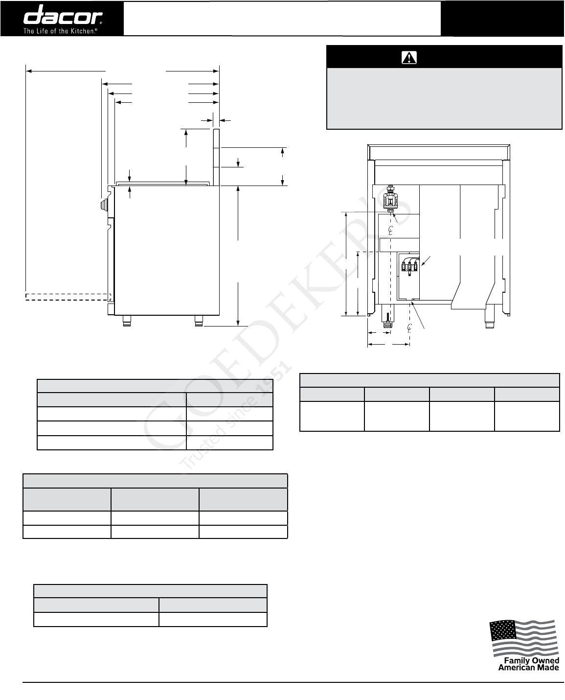
NOTE: This range is NOT designed for self-rimming installation or
installation with a raised vent.
1 1/8” (2.9 cm)
Rear of front panel/oven door
Front of knobs
Front of open door
Front panel
3” (7.6 cm)
Backguard*
6” (15.2 cm)
Backguard**
** Optional
Standard
*
37 7/8”
(96.2 cm)
to
35 3/4”
(90.8 cm)
Width at front panel:
29 7/8” (75.9 cm)
Finished side panel
9” (22.9 cm)
Backguard**
1 1/8” (2.9 mm) to cooking
surface (top of grates) from
top of trim
26 1/2” (67.3 cm)
28 1/2” (72.4 cm)
24 3/8” (61.9 cm)
46 3/8” (117.8 cm)
All tolerances: ±1/16” (±1.6 mm) unless otherwise stated.
WARNING
• Observe all governing codes and ordinances during
planning and installation. Contact your local building
department for further information.
• This appliance must be installed in accordance with
the accompanying installation instructions.
Document # PG05-006 Revised 10/01/10 Page 1/2
* Two 120 Vac hot (L1 and L2), one neutral, one ground
The regulator inlet accommodates a 3/4” gas line. The range ships with a
1/2” to 3/4” adapter connected to the regulator.
Gas - Electrical Access Dimensions
A B C
D
4 3/4”
(12.1 cm)
22 1/8”
(56.2 cm)
8 3/4”
(22.2 cm)
13 3/4”
(34.9 cm)
B
Gas
inlet
A
C
7/8” (2.2 cm) dia. electrical
connection hole in bottom*
D
Range electrical access,
cover removed
GAS AND ELECTRICAL DIMENSIONS
PRODUCT DIMENSIONS
Gas Supply Pressure Requirements*
Gas Type Manifold Pressure
Minimum Gas Supply
Pressure
Natural gas 5” water column 6” water column
LP 10” water column 11” water column
* Maximum input gas supply pressure for all models is 1/2 p.s.i.
7/8" to 1 1/8" dia. access hole